Corner glue flap
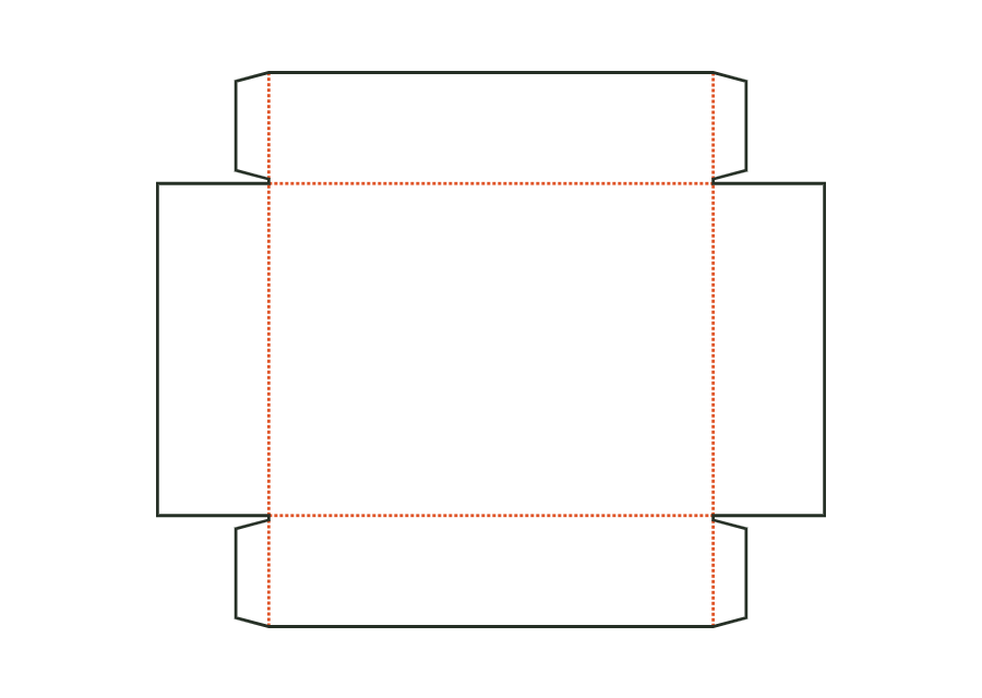
Width of the glue flaps at the ends of the front and back walls, which are glued to the inside of the end walls. The material requires a minimum width; flaps from both sides must not meet on the end wall.
 JetDieline
Trays and displays / JETDIELINE
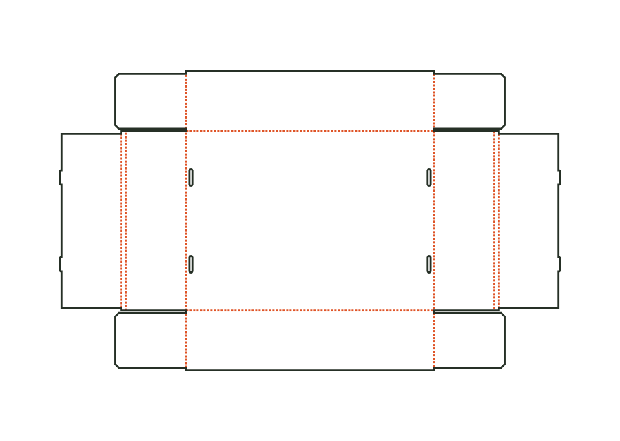
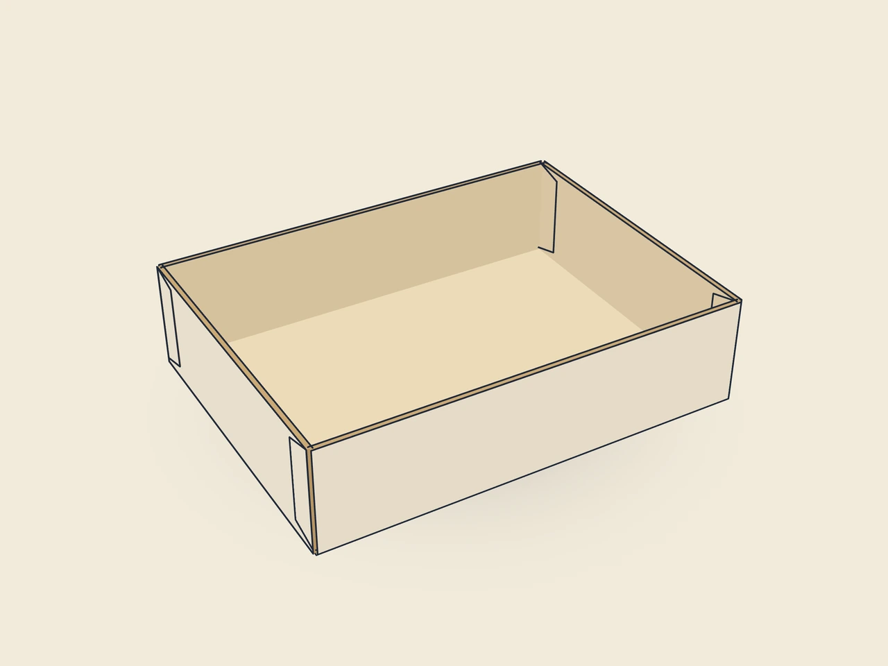
A base, four walls and glued corners form the open folding tray. The page shows V2 with an optional window; the window remains switched off in the starting example.
Drag to rotate
03 / BOX
Simplified display model without material thickness, not to scale.
The 3D view is not available in this browser. The image shows the folded shape.
carton.tray.gluedThe base sits centrally between the front and back walls and the end walls. Four corner glue flaps are folded inward and coated with adhesive. The end walls press against the flaps and close the open corners.
Raise the front and back walls, fold the corner glue flaps inward and coat their outside with adhesive. Raise the end walls and press firmly against the flaps (manually or in a tray erector).
Grain direction horizontal on the blank (check)
Test fit, folding and closure on a sample made from the intended material. Confirm material thickness, grain direction and production steps with your printer.
Inside dimension
These dimensions describe the preview, not a fixed packaging size. The app recalculates the dieline for your own dimensions.
Width of the glue flaps at the ends of the front and back walls, which are glued to the inside of the end walls. The material requires a minimum width; flaps from both sides must not meet on the end wall.
Angle at both ends of the corner glue flaps; prevents the flap from catching on the base or upper edge during erection.
Gap between adjacent flaps or walls; at least about the material thickness.
Enable a display window with a film margin (start: without). It sits in the lid (mailer, hinged lid), front wall (trays) or front (gable, pillow); window, film margin and 3 mm bridge must fit within the panel.
Shape of the window cutout in the front.
Four corner glue flaps on the front and back walls are folded inward and coated with adhesive on the outside. The end walls are then raised and pressed against the flaps. The parametric structure describes this assembly. Adhesive choice, pressing time and actual strength depend on material and processing and must be checked on a sample.
This ID describes glued corners. A separate catalogue type exists for assembly with locking corners. Its rollovers, tabs and slots change the blank. You therefore cannot simply omit the glue. Choose the appropriate structure and check its assembly with the final material.
The page shows V2 of the glued board tray. This version adds an optional window in the front wall. The starting example uses the structure without a window. Template ID, version and selected parameters remain visible in the data. This lets you match the preview to the correct structural version.
Find the right packaging shape and fit it to your product
Design the artwork directly on the real dieline
Spot problems before you pass on files
Files your printer can trace
Unglued tray made from folding boxboard: front and back walls with corner flaps, double end walls with a return; tabs on the inner wall tuck into slots in the bottom.
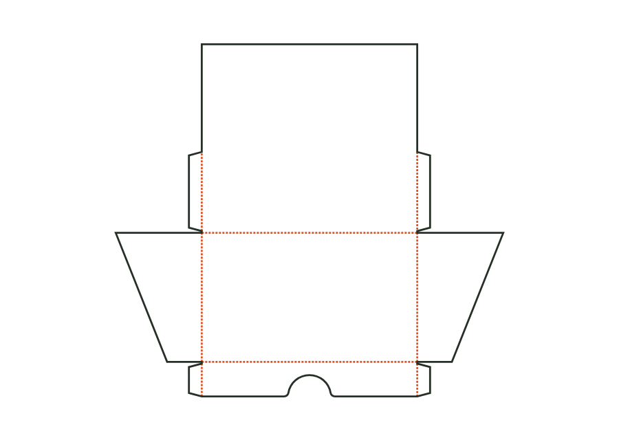
carton.tray.lockedView templateOpen display for the shop counter: low front wall with finger recess, tall back wall with advertising area, sloping side walls; corners are glued inside with corner glue flaps as on the tray.
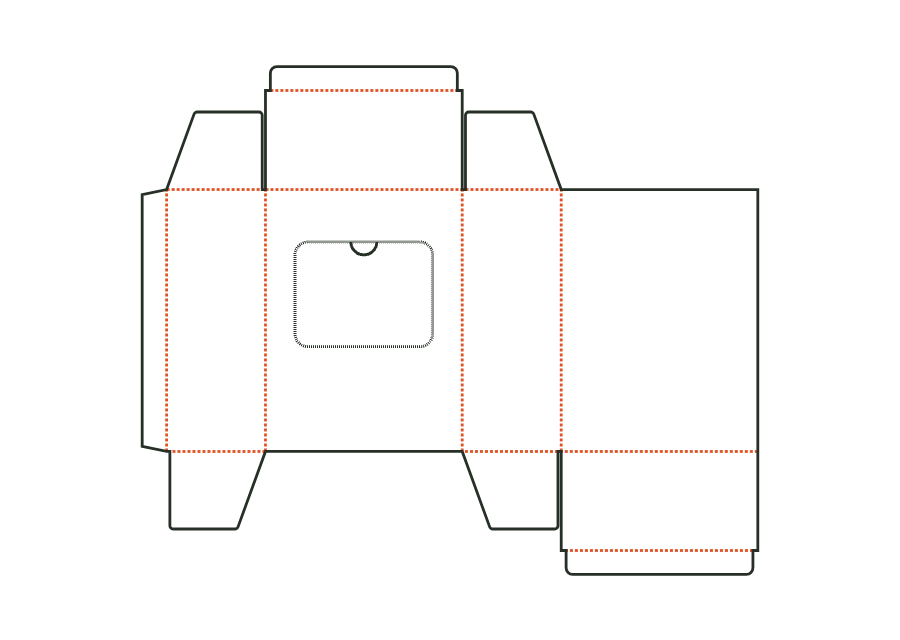
carton.display.counterView templateReverse tuck-end carton with a perforated tear-out window on the front and a thumb notch as a tear tab; after opening, the contents are removed individually.
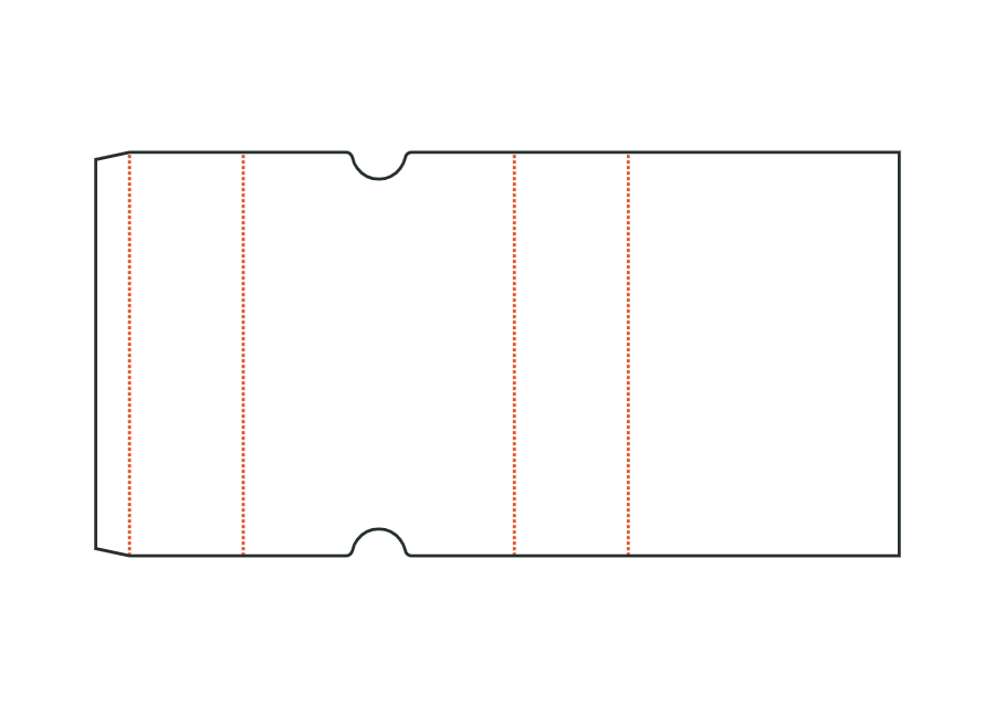
carton.dispenserView templateThe sleeve surrounds a product with four walls and remains open at both ends. Length and width describe the cross-section; height describes the sleeve length. The dieline shows version 1 with finger notches on the front. Material thickness, glue flap and notch position remain part of the calculation rather than simple scaling.
carton.sleeveView templateWith JetDieline, choose a suitable template, adjust its size, and place text, logos, and images directly on your packaging.
Try your dimensions