Corner radius
Radius at all contour corners with at least a 5° direction change; crease line ends remain sharp.
 JetDieline
Paper products and custom contours / JETDIELINE
Blank from your own closed contour (point list, e.g., from an SVG file) with a uniform corner radius and up to four crease lines between contour points; panels are derived from the crease lines.
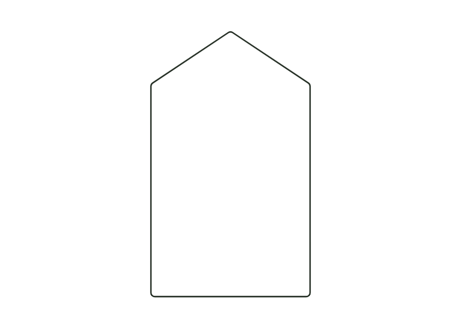
custom.polygonThe starting contour is a gable-shaped card defined by five points. A uniform radius rounds the corners; no crease lines are active in the starting example. Up to four crease lines connect entered contour points. The resulting surfaces are built as panels with folding semantics.
Fold crease lines in numerical order: positive angles inward, negative angles outward.
no recommendation (check)
Test fit, folding and closure on a sample made from the intended material. Confirm material thickness, grain direction and production steps with your printer.
Outside dimension
These dimensions describe the preview, not a fixed packaging size. The app recalculates the dieline for your own dimensions.
Radius at all contour corners with at least a 5° direction change; crease line ends remain sharp.
Number of the contour point where the crease line starts (1 = first contour point); 0 = no crease line.
Number of the contour point where the crease line ends; the line must lie within the contour and must not cross another crease line.
Fold angle of the crease line: positive inward, negative outward; 0° remains flat.
Number of the contour point where the crease line starts (1 = first contour point); 0 = no crease line.
The point list is 0 0; 120 0; 120 160; 60 200; 0 160 in millimeters. It describes a gable-shaped card. The starting corner radius of 3 mm rounds the contour. The measured bounding box is therefore slightly lower than the highest unrounded point coordinate of 200 mm.
Each line has a start point number, end point number, and fold angle. Numbers refer to the entered contour sequence, starting with 1. Zero disables the line. Up to four crease lines are supported. The ends must connect suitable contour points; lines outside or along the outer edge are invalid.
Positive angles fold inward, negative angles outward. Zero degrees remains flat. The sequence follows the crease numbers. These settings belong to folding semantics and do not replace a physical test. Especially with multiple creases, check that the entered sequence suits your intended assembly and target board.
Find the right packaging shape and fit it to your product
Design the artwork directly on the real dieline
See problems before you pass on files
Files your printer can follow
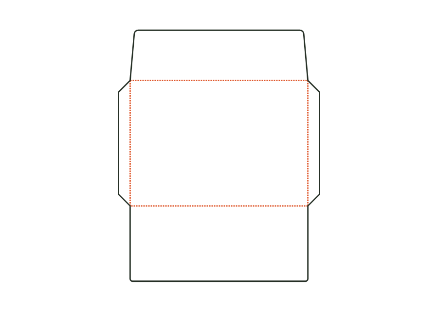
Envelope with an opening on the long side: address panel, two side flaps, bottom flap as the back, and a straight or pointed closure flap. Dimensions refer to the finished size; starting sizes DL, C6, C5, C4, and US No. 10.
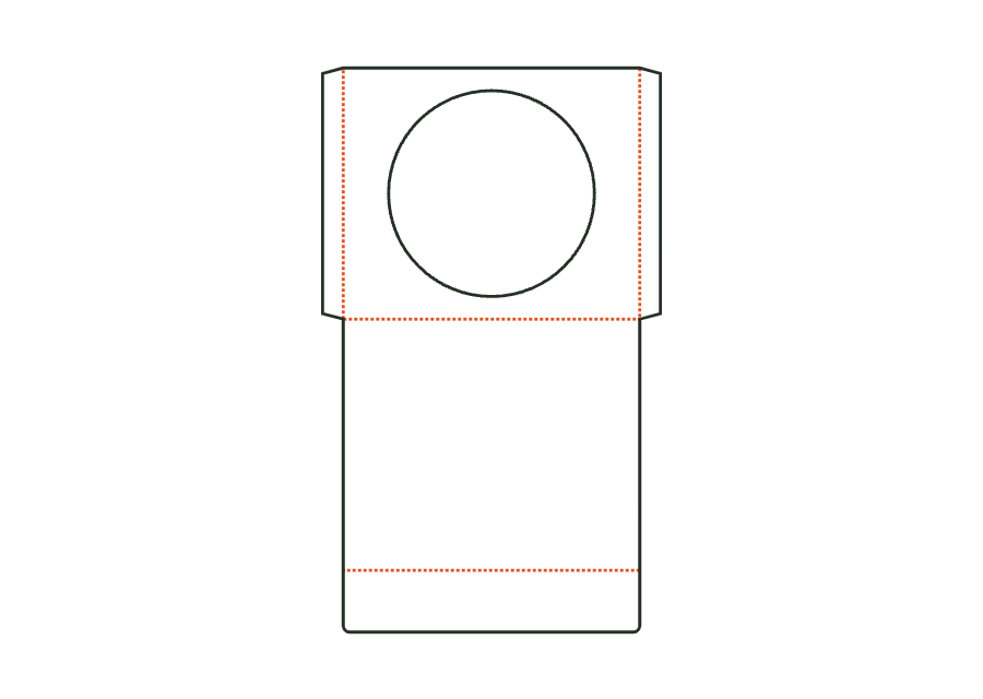
envelope.walletView templateFlat sleeve for a CD or DVD with a round window (optionally without), side seams formed by glue flaps, a closure flap on the back, and an optional thumb notch. Dimensions refer to the insert; clearance and flaps make the sleeve larger.
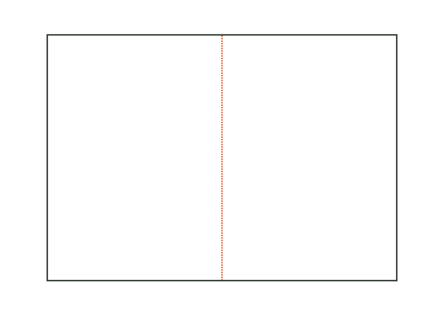
envelope.cdView templateFolded card with a single fold (two panels), roll fold (three panels, with a slightly narrower inner flap), or gate fold (center with two wings). Dimensions refer to the folded finished size.
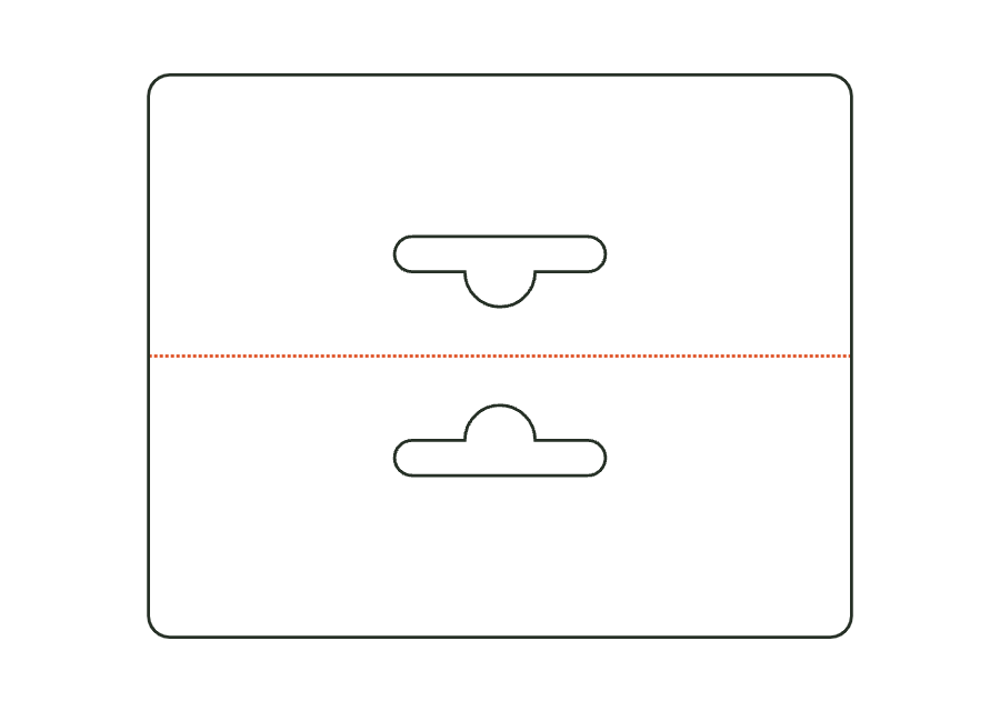
card.foldView templateHeader card folded over a bag's edge and stapled or glued, with a hanging hole through both layers (Euro slot, round hole, or slot). Dimensions are the folded final format.
card.headerView templateWith JetDieline, choose a suitable template, adjust its size, and place text, logos, and images directly on your packaging.
Try your dimensions